Licensing / Pricing <> Program Features <> Free Demo
Features of the PANELS© 4.5 Program
PANELS© 4.5 is a “Stand-alone” Windows XP®, Windows Vista®, or Windows 7®, based program which requires no CAD program, spreadsheet or other similar data program to operate. System requirements do not mandate large memory or special CPU speeds. The graphic display of the computer must be set at 1024 x 768 resolution (or larger) with the small fonts option selected.
PANELS© 4.5 data storage files are compact (5k to 7k average). The program is network ready to allow master data storage on a server which permits sharing by a common network. Data files are locked during edit to ensure data integrity.
PANELS© 4.5 supports the following system voltages and phases:
120/240 volt, Single Phase, Three Wire
120/208 volt, Single Phase, Three Wire
120/240 volt, Three Phase High Leg Delta, Four Wire
208 volt, Three Phase, Three Wire
240 volt, Three Phase, Three Wire
120/208 volt, Three Phase, Four Wire
480 volt, Three Phase, Three Wire
277/480 volt, Three Phase, Four Wire
PANELS© 4.5 has been pre-programmed to be 2008 National Electrical Code compliant. The program will not allow less than code minimum but will allow input which exceeds code requirements. The following tables and information have been integrated into the core logic of the program which is used to size breakers, wires and conduits:
NEC 240-6 Standard Ampere Ratings for fuses and circuit breakers
Table 310-16 for wire sizes – all insulation types and wires are supported
Table 310-16 temperature correction factors are automatically applied
Table 310-15(b)(2)(a) adjustment factors for more than 3 current-carrying conductors
Table 250-122 for sizing equipment grounding conductors
Table 250-66 for minimum sizing of grounding electrode conductor
Table 430-148 for full-load currents for single phase motors
Table 430-150 for full-load current for three phase motors
Table 4 conduit data for EMT, IMC, Rigid Metal, PVC Type A, PVC Schedule 40 & 80 conduits
Table 5 dimensions of insulated, bare conductors and fixture wires used for conduit sizing
The program allows input of multiple loads on a single circuit. For example, a circuit labeled “Bathroom Lighting and Fans” will have a separate input for the lighting and motor load portions of the circuit. This will allow proper and accurate panel diversification calculations.
PANELS© 4.5 calculates code required, minimum circuit breaker size based on NEC 220 branch circuit requirements and automatically selects the applicable NEC section 240-6 standard size breaker. The operator has the option to input larger or custom sized breakers as desired. Based on load calculations and selected circuit breaker, the program selects code required wire size and conduit size. The program will permit the selection of a larger wire size than code requires and will allow the automatic application of NEC 250-122(b) to resize the ground wire. This feature can be toggled off/on as needed. The application of NEC 110-14(c) (temperature limitation of electrical terminal connections) can also be toggled off/on as needed. The edit screen (shown below) illustrates all individual circuit data and allows modifications as necessary.
Each individual circuit permits unique separate wire, insulation, conduit and ambient temperature correction factors to be applied.
Specialty HVAC load input screen (shown below) allows quick and convenient input of loads for the following types of HVAC equipment.
Package unit – straight cool / no heat
Package unit – cooling with electric strip heat
Package unit – cooling with gas heat
Package unit – heat pump with no supplemental heat
Package unit – heat pump with electric supplemental heat
Electric fan coil only
DX Split System – no heat
DX Split System – with electric strip heat
DX Heat Pump – no supplemental heat
DX Heat Pump – with electrical supplemental heat
DX Split System – with gas heat
Where applicable, such as DX cooling with electric strip heaters, the smaller of the electric strip heater or compressor load is automatically diversified from circuit load requirements.
The program supports classic Windows® “click” selection and conventional copy, multi-copy, move, swap, delete and Windows® “clipboard” operations. Editing of existing circuits is fast and convenient with all individual circuit information available for review or edit. After a circuit is selected, the sample screen below provides convenient access to modification operations.
PANELS© 4.5 provides flexible storage and other file operations. The panel options screen (as shown below) allows the setting of automatic save operations and automatic creation of a backup file on each panel save. When the automatic save feature is “ON” all created automatic saves are deleted upon a normal exit from the edit session.
Overall panel schedule setup is made from the master panel options input screen. This screen sets the base values of how new circuits are created and also permits many other customization features to be applied. All features, except the changing of the panel characteristics, are available for modification at any time during panel edit. The panel characteristics option is only available during the initial panel creation.

PANELS© 4.5 generates all graphics to produce a detailed and completed panel schedule. It does not encumber expensive CAD platforms and permits better utilization of staff equipment and resources in larger firms.
Output schedules can be printed on all printers under the control of the Windows® Operating System. Output can be imported to CAD programs which support Windows® TrueType Fonts. A native AutoCAD® shape file is included with the program for efficient use in the AutoCAD® drafting platform.
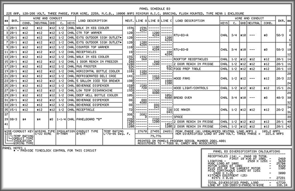
Click here for a larger more detail view of the full panel output. This will open a new tab. Just close that tab when done viewing.
